MagSafe to USB charger
Recently, I came up with the idea of creating something that will let me charge my phone via a MagSafe charger.
The use case for this is a bit limited (since you could just plug the phone into the laptop to charge) but could be handy sometimes when you don’t want to set up a laptop just for charging (like at an airport). Overall, this means needing to pack one less charger. The MagSafe charger cable being quite long (much longer than most USB chargers) can also be a bonus.
The device works by first negotiating with the MagSafe charger to give it power. When full power is given (it outputs 14-20V depending on the model), a buck convertor is used to step down the voltage to 5V that can be used by USB. Finally, a microcontroller is used to control the LED on the connector. I wanted the charger to be able to source at least 1.5A to the USB device.
At this point, I’d also like to add that the article about MagSafe written by Ken Sheriff was immensely helpful in developing this.
The first challenge of using MagSafe is that it has some safety features built in that prevents short circuits from becoming dangerous. Ken’s article details exactly what needs to be done to negotiate power from the charger. In short, on the first connection, the charger outputs either 6V or 3V (depending on model) that’s current limited to about 100uA. During negotiation, a resistive load is applied to the input that drops the voltage down to about 1.7V for one second. After that, the charger delivers full power.
The problem is that the rest of the circuit must be switched off with minimal leakage current until power negotiation is finished. To solve this, I configured a N-channel MOSFET to only turn on the rest of the circuit after power negotiation.
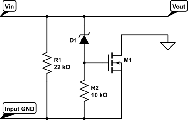
R1 is the resistor that will be used in power negotiation. D1 is a zener diode that will drop roughly 6.3V. In other words, if the voltage is less than 6.3V, the gate of the MOSFET will be pulled low by R2.
During power negotiation, the maximum voltage that will be output will be 6V so the voltage potential at the gate will be 0V which will keep the MOSFET switched off. After power negotiation, the voltage potential at Vin will be at least 14V. D1 will drop 6.3V, leaving roughly 8V at the gate of the MOSFET, switching the rest of the circuit on.
After power negotiation, things become very straightforward. My first thought was to just throw on a linear regulator but I quickly realised this would dissipate tremendous amounts of heat at higher loads (at 20V input voltage, we’re dropping 15V - at 1A current draw, we’re dissipating 15W of heat. Yikes!).
The buck regulator is pretty standard. I chose an AP1509 chip for ease of implementation. It’s supposed to be able to deliver 2A on its own.
Next up was the microcontroller. The microcontroller is supposed to communicate with the chip on the MagSafe connector via 1wire to set the colour of the LED. I chose an ATtiny85 for this since they’re readily available, have a low pin count and very easy to program with the Arduino software. The microcontroller just taps off the 5V output from the buck converter and uses an internal oscillator for its clock. The part count is very little. It just uses some pull-up resistors for the reset line and 1wire pin.
For current sensing, I opted for the ACS713. It’s a little pricey and overkill for the project but it’s very easy to use and has a small part count (just one filter cap). It outputs 500mV on no load and has a sensitivity of about 150mV per amp.
Normally, you’d want to pipe the output of the ACS713 to an amplifier before connecting it to a microcontroller to get the full range of input. However, I wanted to minimise parts so I had to use a trick to interface it to the ATtiny. The trick is to set the reference voltage of the ADC on the ATtiny to the internal 1.1V reference. That will give more than enough range for the ATtiny to detect a load.
I configured the ATtiny to set the LED to green if the current draw falls below a certain threshold. I’m still trying to calibrate it correctly but generally, it’ll turn green when the load drops to less than 100mA. Otherwise, the LED is set to orange. I actually forgot to put a filter cap near the ADC input pin so I had to take multiple readings and average it to get the right value but it worked fine in the end.
In the interests of safety, I also opted to put a polyfuse in line with the charger input in case something shorted out in the rest of the circuit. The MagSafe charger is capable of delivering huge amounts of power (85W on mine) and can completely ruin your day if something shorts out and catches on fire.
To prevent a USB device from drawing too much current, I also added a RT9701 USB current limiting switch to prevent a device from drawing too much power.
Last but not least, I needed a reliable way of connecting the MagSafe connector to my circuit. As you might’ve guessed, it was impossible to find MagSafe jacks for use in hobby projects. I ended up ordering cheap OEM replacement MagSafe boards on Aliexpress and rewiring them.
Finally, I put everything together on a custom made PCB (black soldermask to match the Apple replacement part :3) and watched it work!
So, that’s my first revision of the board. Unfortunately, the thing generates a whole ton of heat when my phone starts to draw around 0.7 amps. I haven’t measured the efficiency of the buck convertor but I’m sure it can be improved.